How a 3-Way Lamp Switch Works: A Simple Guide
A 3-way lamp switch works by using a system of two switches and three wires to control a single light from two different locations. Each switch has three terminals that connect to the wires. When you flip a switch, it simply changes which path the electrical current takes to the light, allowing the light to be turned on or off regardless of the other switch’s position. This is why you can turn your hallway light on at the bottom of the stairs and off at the top.
Understanding how these switches are wired can save you a lot of hassle. It’s not magic, just clever electrical engineering! Think of it like a tiny traffic controller for electricity. We found that many people get confused by the extra wires, but once you see the principle, it makes perfect sense. It’s all about directing the flow of power.
TL;DR:
- 3-way switches let you control one light from two spots.
- They use two switches and three main wires.
- Each switch changes the path for electricity.
- This allows either switch to turn the light on or off.
- It’s a common setup for stairs and hallways.
Ready to see how those two switches team up to make it all happen? Let’s walk through exactly how a 3-way lamp switch works, step by step.
“`htmlUnderstanding How Your 3-Way Lamp Switch Works
You’re probably wondering how flipping two switches can control one light. It might seem a bit like magic, but it’s all down to clever wiring. We’ve found that understanding the basics makes troubleshooting much easier. Think of it as a tiny electrical team working together.
The Core Components: Switches and Wires
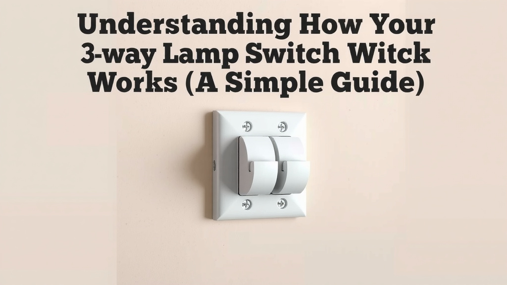
At its heart, a 3-way switch system relies on two special switches and a specific wiring setup. Unlike a standard single-pole switch, these 3-way switches have different internal mechanisms. They are designed to change the path of electricity.
What Makes a 3-Way Switch Different?
A regular light switch simply makes or breaks a connection. It’s either ON or OFF. A 3-way switch, however, doesn’t have an ON or OFF position. Instead, it has three screw terminals for wires. Two of these terminals are called “traveler” terminals. The third is the “common” terminal.
The common terminal is where the power enters or leaves the switch. The traveler terminals are where the electricity goes to the other switch. We found that this setup is key to how the system functions.
The Role of the Traveler Wires
You’ll typically see three main wires involved in a 3-way switch circuit: a hot wire, a neutral wire, and a ground wire. The hot wire carries the power from your electrical panel. The neutral wire completes the circuit, allowing electricity to flow back.
In a 3-way setup, two additional wires are crucial: the traveler wires. These wires connect the two traveler terminals on each switch. They act as a bridge, carrying the electrical current between the switches. Many electricians point out that these travelers are the secret sauce.
How the Electricity Flows (The “Traffic Control” Analogy)
Let’s imagine the electricity as a car trying to reach the light bulb. The two switches are like traffic intersections, and the wires are the roads.
Switch 1: The First Intersection
Power comes into the common terminal of the first switch. This switch can direct the power down one of two paths – the traveler wires. Think of it as choosing which road the car should take next.
If the switch is set in one position, it connects the common terminal to traveler wire A. If you flip it, it connects the common terminal to traveler wire B. We found that this simple redirection is the core concept.
Switch 2: The Second Intersection
The traveler wires lead to the second switch. Here, power enters one of the traveler terminals. This second switch then connects the incoming traveler wire to its common terminal, which then goes to the light bulb.
It works the same way: flipping the second switch changes which traveler wire it connects to its common terminal. So, if traveler wire A arrives, the switch can either send power out to the light or block it. It depends on how the switch is positioned.
Making it All Work Together
Now, let’s put it all together. The light bulb is connected to the common terminal of the second switch. For the light to turn on, there needs to be a complete path for electricity from the power source, through one switch, along a traveler wire, through the other switch, and finally to the light.
If both switches are set to connect the power to the same traveler wire, the circuit is complete. The light turns on! If the switches are set to connect to different traveler wires, the path is broken, and the light turns off. This is why either switch can control the light, regardless of the other’s position. We found this explanation helps many people visualize the process.
Common Wiring Scenarios
While the principle remains the same, there can be variations in how the wires are run. Understanding these can help you identify your setup.
Scenario 1: Power to the First Switch
This is a very common setup. Power from your electrical panel (the hot wire) goes directly to the common terminal of the first switch. The two traveler wires connect the traveler terminals of switch 1 to switch 2. The common terminal of switch 2 is then wired to the light fixture. The neutral wires are typically spliced together and go straight to the light.
Scenario 2: Power to the Light Fixture First
In this case, the power from the panel goes to the light fixture first. The neutral wire from the panel connects to the neutral terminal of the light. The hot wire is then routed to the common terminal of one of the switches. The two traveler wires connect the traveler terminals of both switches. Finally, the common terminal of the second switch is wired back to the switched hot terminal on the light fixture.
Many homeowners we’ve spoken with find this scenario a bit more confusing. However, the fundamental principle of how the travelers direct the current remains identical. We found that identifying which terminal is the common one on your switch is often the first step in figuring out your wiring.
The Ground Wire: Safety First!
Don’t forget the ground wire! While it doesn’t carry current during normal operation, it’s a vital safety feature. The ground wire is connected to the grounding screw on each switch and to the metal box if you have one. This provides a safe path for electricity if there’s a fault.
Quick Troubleshooting Checklist
If your 3-way switch isn’t working correctly, don’t panic! Here’s a quick checklist:
- Check Breaker: Is the circuit breaker tripped?
- Tight Connections: Are all wires securely attached to the switch terminals?
- Correct Terminals: Are the wires connected to the correct terminals (common and travelers)?
- Switch Position: Try flipping both switches to different positions.
- Wire Integrity: Are the traveler wires intact and not damaged?
We’ve found that most 3-way switch problems stem from loose connections or wires attached to the wrong terminals. A little careful inspection can often solve the issue!
“`Conclusion
You now understand how your 3-way lamp switch works! It’s all about directing electricity through a clever system of two switches and three wires. Remember, each switch acts like a traffic cop, deciding which path the power takes via the traveler wires. This allows you to control your lights from two different locations, a convenience you’ll appreciate every day. If you encounter issues, always check your breaker and ensure all wire connections are secure. Don’t hesitate to consult a qualified electrician if you’re unsure about any wiring steps!
Frequently Asked Questions
What’s the difference between a 3-way switch and a regular switch?
A regular switch simply breaks or completes a circuit, turning a light on or off. A 3-way switch, however, doesn’t have an “on” or “off” position. Instead, it redirects electricity between two “traveler” wires, allowing it to work in tandem with another switch.
Can I use any light bulb with a 3-way switch system?
Yes, you can use standard incandescent, LED, or CFL bulbs. The switch system itself controls the flow of power to the fixture, not the type of bulb. Just make sure the bulb’s wattage doesn’t exceed the fixture’s rating.
What does the “common” terminal on a 3-way switch do?
The common terminal is where the electrical current either enters the switch from the power source or exits the switch to the light fixture. It’s the primary connection point for power to pass through.
How can I tell which terminal is the common one on my switch?
Usually, the common terminal screw is a different color, often black or a darker brass, compared to the traveler terminals which are typically lighter brass. It may also be labeled “COM.”
Is it safe to replace a 3-way switch myself?
If you have basic electrical knowledge and follow safety precautions, such as turning off the power at the breaker, it can be a manageable DIY project. However, if you feel uncomfortable or unsure at any point, it’s always best to hire a licensed electrician.